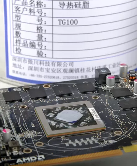
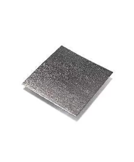
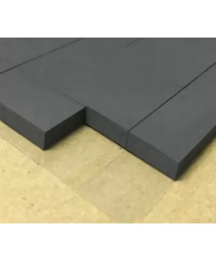
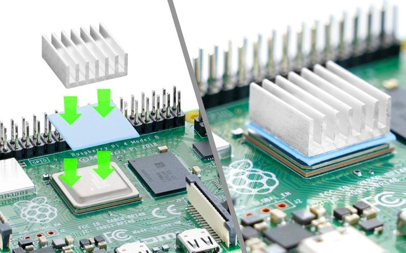
For fragile packages and board-mounted components, thermal-interface selection is also a mechanical protection task. The material must maintain a heat path across production tolerances without loading the component, solder joints, PCB, or mounting hardware beyond the assembly limit.
Establish the minimum, nominal, and maximum interface gaps using component height, board thickness, heat-sink flatness, housing dimensions, and mounting features. Use these boundaries to select an initial material thickness and compliance, then confirm contact and component load in representative assemblies. A low-compression-force thermal pad may suit a design with limited load margin, but softness alone does not establish suitability.
Evaluate thickness and compression behavior together. A thicker pad may bridge a wider gap, but the resulting deflection and retention conditions also matter. Confirm the selected grade and bond-line in the actual assembly; do not stack materials or substitute thicknesses without rechecking the fit. If the interface must electrically isolate the component from the heat sink, verify the selected grade’s dielectric properties as well as its thermal performance.
Thermal conductivity and electrical behavior are separate specifications. Verify dielectric strength or volume resistivity when isolation is required, using data for the exact grade. An electrically conductive interface should be considered only when the design intentionally requires an electrical path and the system’s safety requirements have been reviewed.
Use supplier compression-deflection data to screen candidates, then test the intended thickness between the actual mating surfaces. Record the mounting method and fastener conditions. Torque is only an indirect indicator of interface pressure because friction and joint geometry vary. AOK’s published TP1200 data lists thermal conductivity of 12.0 W/(m·K); treat this as a grade-specific screening value, then confirm performance and load at the intended thickness and assembly conditions.
| Format | Potential fit | Verify |
| Preformed pad | Controlled thickness and quick placement | Compression behavior, gap range, insulation, retention |
| Insulating sheet | Electrical isolation and cut-to-shape handling | Dielectric data, thickness tolerance, cut-through resistance |
| Dispensed gap filler | Irregular gaps or variable component heights | Dispense repeatability, pressure, bond-line and cure control |
| Grease or gel | Thin interfaces or specific surface-contact needs | Application control, migration, rework and compatibility |
Test representative builds at the tightest and widest expected gaps. Monitor temperature, inspect contact where practical, and check for over-compression or component stress. Include removal and replacement in validation when the product may be reworked or serviced.
Document the approved grade, thickness, outline, orientation, liner-removal sequence, surface preparation, mounting sequence, fastener conditions, and inspection method. For dispensed materials, also specify mix ratio where applicable, dispense pattern, bead volume, open time, and cure conditions. Review substitutions for their effects on gap fill, pressure, electrical safety, and thermal response.
No. Force depends on compression behavior, thickness, contact area, and mounting geometry.
No. Torque is indirect and depends on friction and joint design. Use a controlled assembly method and verify representative builds.
The minimum gap can reveal excessive compression; the maximum shows whether contact is maintained.
No. Confirm each requirement from the selected grade’s technical data.
Release a thermal interface for fragile electronics only after qualifying the mechanical stack-up and thermal path together. Test tolerance extremes, confirm contact without overloading sensitive components, and convert the successful build into a controlled assembly specification. AOK can help identify candidate materials for representative application testing.

 +86 755 2976 5899


 English