There is no universal thermal pad thickness for every M.2 NVMe SSD. The correct thickness is the smallest pad thickness that completely bridges the gap between the SSD components and the heatsink while still allowing the cooler to sit in its designed position.
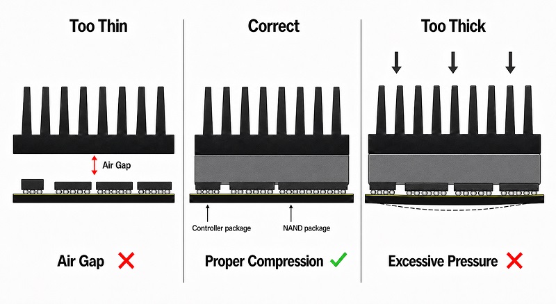
If your motherboard or M.2 heatsink includes a thermal pad, the safest starting point is to use the supplied pad. Kingston also advises using the thermal pad supplied with the M.2 shield or heatsink and ensuring full, even contact. A pad that is too thick can reduce mounting pressure, while one that is too thin may fail to maintain proper contact.
For replacement applications, 0.5 mm, 1.0 mm and 1.5 mm are common thickness options, but they should not be treated as universal specifications. Different SSDs, motherboards and heatsinks create different physical gaps.
The objective is simple:
SSD component → compressed thermal pad → heatsink
There should be complete contact, moderate compression and no unwanted bending of the SSD.
An M.2 2280 SSD may have the same external length and width as another M.2 2280 SSD but still have a different component height.
The controller, NAND flash packages and DRAM do not necessarily have identical Z-heights across different SSD designs.
This matters because the heatsink is normally positioned at a fixed height.
Recent testing of 20 modern motherboards illustrates the problem. Only 6 of the 20 tested boards produced what the testers considered good thermal contact across the SSD, while other boards had light, partial or poor contact.
The same investigation summarized M.2 component-height categories showing that single-sided SSD component heights can range roughly from 1.2 to 2.0 mm above the PCB, depending on the design class. Double-sided drives also vary on both the top and bottom surfaces.
The key question is not whether 1 mm or 1.5 mm is better, but which thickness provides complete contact in your specific SSD-and-heatsink assembly.
The following table should be treated as a selection framework rather than a universal specification.
Situation | Thickness Approach | What to Verify |
Original motherboard pad is available | Use the original specification | Full contact and normal heatsink seating |
Heatsink includes its own pad | Use the supplied pad first | Pad imprint after installation |
Very small component-to-heatsink gap | Thin pad may be required | Pad is actually compressed |
Moderate gap | 1.0 mm-class pads are commonly evaluated | Heatsink sits flat |
Larger gap | 1.5 mm or thicker may be required | SSD PCB is not bending |
Unknown gap | Measure or perform a contact test | Do not guess from another SSD model |
Single-sided SSD | Usually focus on the component side | Controller and NAND contact |
Double-sided SSD | Check both sides if the cooler supports them | Bottom components are not overstressed |
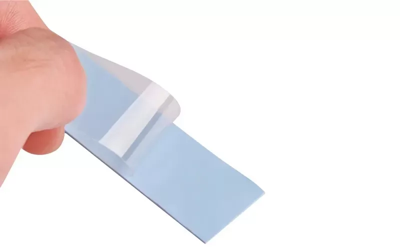
AOK itself offers thermal pads in multiple thickness ranges and, depending on the series, thicknesses are available in 0.25 mm increments, allowing engineers and OEM customers to match the material more closely to the mechanical design.
It can be—but only when the physical gap is small enough.
For example, AOK's TP150-H55-S silicone thermal pad is available from 0.5 mm, while the broader TP150 family is specifically listed for applications including memory modules and NVMe SSDs.
A thin thermal pad can be beneficial because thermal resistance through the bulk material increases with thickness.
For one-dimensional heat conduction:
R = t / (k × A)
where:
R = bulk thermal resistance
t = material thickness
k = thermal conductivity
A = heat-transfer area
For the same conductivity and contact area, a thinner thermal interface produces lower bulk resistance.
But that advantage disappears if the pad becomes so thin that it no longer contacts the heatsink.
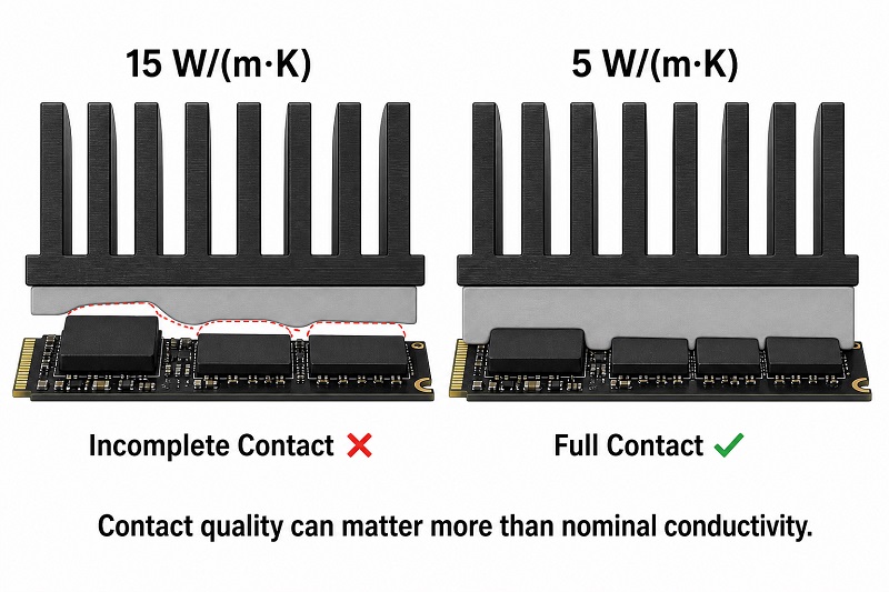
A 0.5 mm pad with an air gap is worse than a correctly fitted 1.0 mm pad.
This is why fit should be determined before conductivity or thickness is optimized.
A 1.0 mm thermal pad is frequently encountered in electronics cooling because it can bridge a moderate mechanical gap while still being thin enough to avoid excessive thermal resistance.
AOK has multiple pad families that cover this size.
For example:
TP150 series includes 1.0 mm and other thickness options.
TP200 series includes grades starting at 0.5 or 1.0 mm depending on formulation.
TP500 series covers approximately 0.5–6.0 mm in its published technical information.
TP1000 covers approximately 0.4–5.0 mm.
However, a 1.0 mm pad should still not be selected simply because it is common.
The heatsink must produce visible, even contact.
A 1.5 mm thermal pad may be appropriate where the SSD components sit farther below the heatsink.
It may also help when an integrated motherboard M.2 shield has insufficient contact with a thinner SSD.
However, increasing thickness introduces another risk.
If the pad is too thick or too hard, the heatsink can apply excessive force to the SSD or may fail to reach its intended installed position.
In extreme cases this can:
bend the M.2 PCB
increase stress on soldered components
lift one side of the heatsink
create uneven controller contact
make the mounting screw difficult to install correctly
AOK's existing thermal-pad guidance likewise emphasizes that thickness should be determined by the actual gap between the heat source and the cooling surface rather than selected independently.
For an engineering or OEM project, the best method is to determine the actual mechanical gap.
This should always be the first option.
If the supplier specifies the pad thickness, use that value unless the SSD geometry has changed from the intended design.
Determine the distance between:
the top of the controller/NAND/DRAM package
and the corresponding heatsink surface
The thermal pad should be thick enough to bridge this gap after assembly.
For servicing or prototype validation, install the pad and heatsink once, then remove them carefully.
Look at the pad surface.
A good result should show:
visible contact
reasonably even compression
contact over the important heat-generating components
no evidence of extreme crushing
If there is no imprint, the pad may be too thin.
If the pad is severely displaced or the SSD visibly bends, it may be too thick or too stiff.
Thermal pads work partly because a soft material conforms to microscopic and macroscopic surface differences.
Henkel describes thermal gap pads as soft, conformable materials used to eliminate air gaps between electronic components and cooling surfaces.
A pad that simply touches both surfaces without conforming may still leave microscopic voids.
But more compression is not automatically better.
The required force depends strongly on pad hardness.
A soft pad may deform substantially under low force, while a harder high-conductivity pad may generate considerably more stress for the same compression percentage.
This is why professional thermal-material selection considers both:
thermal conductivity + compression-force behavior
rather than conductivity alone.
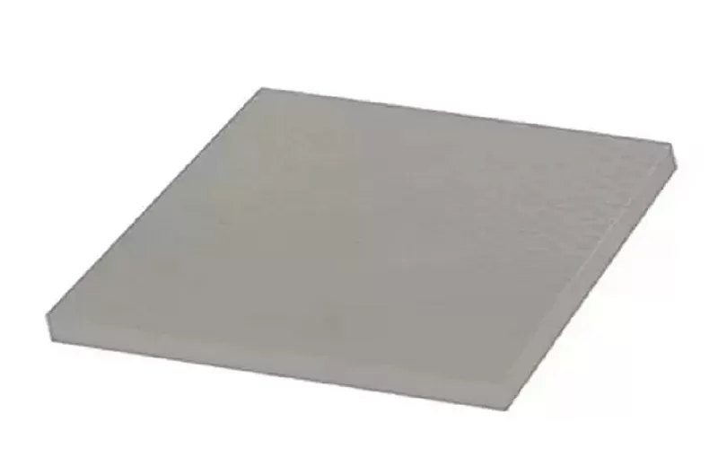
For SSD manufacturers, heatsink suppliers and electronics OEMs that require controlled thicknesses or custom die-cut geometries, AOK operates as a thermal pad manufacturer with sheets and custom-cut components available for different assembly requirements.
You should also determine whether the SSD is single-sided or double-sided before choosing the pad arrangement.
The controller, NAND and DRAM are located primarily on the top side.
In many desktop systems, the main thermal interface is therefore between the top components and motherboard heatsink.
Components exist on both sides of the PCB.
A cooling assembly designed for double-sided SSDs may therefore use thermal pads both above and below the drive.
ARCTIC, for example, specifically designs its M2 Pro cooler for both single- and double-sided M.2 2280 SSDs and uses thermal pads to compensate for differences in device height.
Do not automatically install a thick bottom pad where the motherboard or cooler was not designed for one. Excessive bottom pressure can bend the SSD toward the top heatsink.
The controller is usually one of the most important heat-generating parts of a high-performance NVMe SSD.
Where possible, the thermal solution should produce good contact over the intended heat-generating components rather than touch only one arbitrary point.
The 2026 motherboard contact test found that several heatsinks contacted only the controller or only some NAND packages, demonstrating how easily uneven component height can create incomplete cooling contact.
For an engineered solution, the pad geometry should therefore be matched to:
controller position
NAND position
DRAM position where applicable
heatsink footprint
SSD component height
AOK's conductive silicone pads are available in multiple softness and conductivity grades, and selected pad families can be supplied as custom die-cut parts rather than only rectangular sheets.
Not because of PCIe generation alone.
PCIe generation affects potential performance and power, but thermal pad thickness is fundamentally a mechanical dimension.
A PCIe 5.0 SSD does not automatically require a thicker pad than a PCIe 4.0 SSD.
What may change is the importance of cooling.
Recent high-performance PCIe 5.0 drives can generate substantial heat during sustained workloads, making reliable heatsink contact more important. In one recent test, an uncooled PCIe 5.0 SSD throttled during sustained transfer and its transfer rate dropped significantly after heating.
The correct response is not necessarily “use a thicker pad.”
It is:
achieve complete contact,
select suitable conductivity,
ensure sufficient heatsink capacity,
maintain airflow.
Always follow the SSD manufacturer's specification.
As one concrete example, Samsung specifies an operating range of 0°C to 70°C for the 990 PRO NVMe SSD and recommends proper airflow.
Crucial similarly states that the specified operating range for most of its SSDs is 0°C to 70°C.
These figures should not be treated as a universal throttling threshold for every NVMe controller. Different SSDs use different firmware and thermal-management strategies.
The correct approach is to monitor the drive using manufacturer software or S.M.A.R.T. data and compare the result with that specific SSD's specification.
AOK has developed thermal-management materials since 2004 and supplies multiple silicone thermal-pad families for consumer electronics, networking equipment, computing hardware and storage-related applications.
The TP150 and TP200 series specifically list NVMe SSD / SSD applications in their published use cases. TP150 provides 1.5 W/(m·K) conductivity with highly compliant options, while TP200 provides 2.0 W/(m·K) grades with soft Shore 00 hardness values as low as 25 for selected formulations.
Where higher heat-transfer capability is required, AOK also offers 5, 10, 12 and 15 W/(m·K) pad families.
For B2B buyers evaluating multiple storage or cooling designs, experienced thermal interface material manufacturers should be able to discuss not only W/m·K, but also thickness tolerance, hardness, compression, electrical insulation, die-cut geometry and production consistency.
It can be, provided a 1 mm pad produces complete contact between the SSD components and the heatsink without excessive compression. It is not a universal M.2 specification.
Not necessarily. Some assemblies need approximately this thickness or more, while others require less. If a 1.5 mm pad causes the SSD PCB to bend or prevents the heatsink from seating normally, it is too thick or too stiff for that assembly.
Yes, if the actual component-to-heatsink gap is small enough. AOK has selected pad grades available from 0.5 mm, including products listed for NVMe and storage applications.
Some compression is normally desirable because it helps a compliant pad conform to the SSD and heatsink surfaces. The correct compression depends on the material's hardness and compression-force curve; excessive compression should be avoided.
An excessively thick or stiff pad can place unnecessary force on the M.2 PCB and may prevent the heatsink from reaching its correct position. Always check the SSD for bending after installation.
No. Component Z-height varies between SSD designs, and heatsink geometry varies between motherboards and aftermarket coolers. Use the manufacturer specification or validate the actual physical gap.
The best thermal pad thickness for an M.2 NVMe SSD is not a fixed number such as 0.5 mm, 1.0 mm or 1.5 mm.
It is the thickness that produces complete, even contact after assembly without forcing the SSD or heatsink out of position.
Use the original motherboard or heatsink pad whenever possible. If replacement is necessary, evaluate the actual gap, SSD component height, pad softness and compression behavior before selecting thickness.
For an NVMe cooling design, the correct order is:
fit first → compression second → thermal conductivity third.
A perfectly specified 10 W/(m·K) thermal pad cannot transfer heat effectively if it does not touch the heatsink.
For OEM storage products, motherboard cooling solutions or other high-volume electronics applications, AOK can provide different thermal-pad thicknesses, conductivity levels and custom die-cut geometries to match the mechanical and thermal requirements of the final assembly.

 +86 755 2976 5899

 English