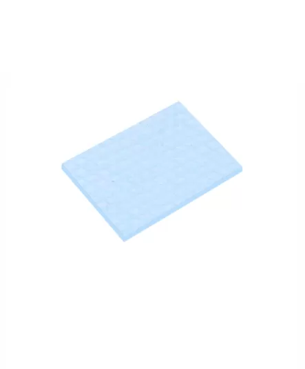
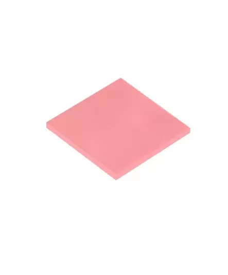
A heat sink insulation pad helps electrically separate a component from a conductive heat sink while allowing the assembly to meet its thermal-management requirements. In power electronics, this balance is important because the material must provide the required electrical isolation without introducing unacceptable thermal resistance. Selecting a suitable pad involves more than checking whether a material is described as insulating. Engineers should evaluate voltage requirements, thermal performance, thickness, mounting pressure, and environmental conditions before approving a material for production.
Power semiconductors and other electronic components may generate significant heat during operation. A metal heat sink provides a path for dissipating that heat, but direct contact between conductive component surfaces and the heat sink may be unsuitable for some electrical designs. A heat sink insulation pad provides an insulating interface where the design requires electrical separation. Some materials are also designed to conduct heat across the interface, helping the assembly manage both electrical and thermal requirements. These functions must be evaluated separately. Thermal conductivity describes how readily heat moves through a material, while dielectric properties characterize its ability to withstand electrical stress under specified conditions. A good result in one category does not automatically establish suitability in the other. The correct design depends on the component, working voltage, heat load, mounting arrangement, and applicable safety requirements. The pad must also remain intact during installation and operation. Material selection should therefore be treated as part of the complete insulation and thermal-management system.
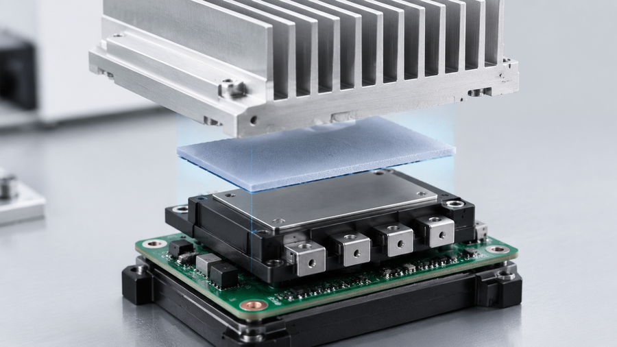
The first step is to establish the electrical requirements. Identify the working voltage, required dielectric withstand, applicable safety criteria, and any relevant resistivity requirements. Confirm that the proposed material's documented properties match the intended operating conditions. Next, evaluate the thermal interface. The most important considerations include:
Thermal conductivity: Review the documented value and test method.
Thermal resistance: Consider the material thickness and installed interface conditions.
Dielectric performance: Confirm the required electrical test data for the specific grade.
Thickness and tolerance: Ensure the material fits the measured gap and assembly tolerances.
Mechanical properties: Check compression, hardness, puncture risk, and surface conditions.
Environmental durability: Evaluate operating temperatures, humidity, vibration, and aging where relevant.
Thickness creates an important design trade-off. A thicker layer may change the electrical insulation margin, but it can also increase thermal resistance. A thinner layer may support heat transfer but require tighter control of surfaces, assembly pressure, and dimensional tolerances. Engineers should verify the complete interface rather than optimizing a single specification in isolation.
A general insulating sheet is primarily selected for its barrier function. A thermally conductive insulation pad is intended for applications where heat must also cross the electrically insulating interface. Neither option is universally better. The correct choice depends on whether heat transfer through the layer is a major requirement and how the electrical, mechanical, and thermal constraints interact.
| Design factor | General insulating sheet | Thermally conductive insulation pad |
|---|---|---|
| Main purpose | Electrical separation or barrier function | Electrical separation combined with heat transfer |
| Thermal performance | Must be assessed for the specific material | Designed for thermal-interface use; verify the selected grade |
| Thickness selection | Based on insulation and mechanical needs | Balances dielectric requirements and thermal resistance |
| Mechanical fit | Depends on material stiffness and dimensions | Depends on grade, compression, and installation conditions |
| Qualification | Electrical, mechanical, and environmental checks | Electrical, thermal, mechanical, and environmental checks |
| Best suited to | Designs where heat transfer through the layer is not a major requirement | Designs requiring heat transfer across an insulated interface |
This comparison describes typical design intent rather than guaranteed product performance. Always consult the technical data sheet for the exact material under consideration.
A material may meet its documented specifications but still fail to perform as intended if the assembly process is poorly controlled. Sharp edges, burrs, uneven mounting pressure, contamination, or misalignment can damage the pad or reduce interface consistency. Incorrect thickness can also create problems, including poor thermal contact or mechanical interference. A practical validation process should include the following steps:
Measure the actual interface gap and review dimensional tolerances.
Confirm the material's dielectric and thermal specifications.
Check the mounting arrangement, surface condition, and pressure limits.
Test the installed interface under representative operating conditions.
Inspect the material after any required environmental exposure.
Document the approved part number and revision for production.
For equipment subject to formal electrical safety requirements, use the applicable standards and qualification procedures. An insulation pad should not be treated as a substitute for required creepage distances, clearance distances, or other design safeguards.
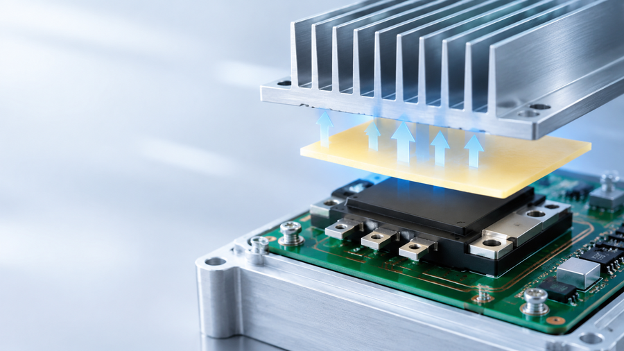
AOK Technologies offers a dedicated Thermal Insulation Pads product range for applications requiring evaluation of electrical insulation and thermal-interface performance. When comparing candidate materials, confirm the current technical data sheet for the exact model. Pay particular attention to dielectric performance, thermal conductivity, thickness, mechanical characteristics, and environmental limitations. Product names alone are not sufficient to establish that a material meets a specific design requirement. The wider AOK Technologies product catalogue can help engineers compare available thermal-interface material categories. For a technical consultation, provide the working voltage, required dielectric test criteria, heat load, interface gap, thickness limits, mounting pressure, operating temperature, and a drawing if available. If the application is governed by a particular safety standard, identify the applicable requirements so the proposed material can be evaluated against the correct criteria.
A heat sink insulation pad must satisfy electrical isolation requirements while supporting the thermal and mechanical needs of the complete assembly. Start by defining the electrical criteria, then evaluate thermal resistance, thickness, compression, and environmental durability. Validate the selected material under representative conditions and control approved part revisions during production. AOK Technologies' Thermal Insulation Pads range offers options for evaluation, but the final grade should be confirmed through current technical documentation and application-specific testing.
Does thermal conductivity indicate how much voltage a pad can withstand?
No. Thermal conductivity and dielectric performance are different properties and must be assessed independently.
Can an insulation pad replace required electrical clearances?
No. The complete design must satisfy the applicable electrical safety requirements.
Is a thicker pad always the safer option?
Not necessarily. Thickness affects both assembly fit and thermal resistance, while electrical suitability depends on the complete design.
What can damage an insulation pad during installation?
Sharp edges, punctures, contamination, misalignment, and excessive localized pressure can compromise its performance.
Are all thermal insulation pad materials interchangeable?
No. Different grades may have different thermal, electrical, mechanical, and environmental characteristics.
What should I provide when requesting a product recommendation?
Share the voltage requirements, dielectric criteria, heat load, interface dimensions, operating environment, and relevant drawings.

 +86 755 2976 5899


 English